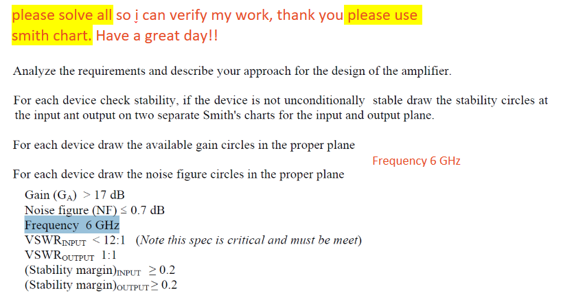

The fzero function always tries to achieve a value of zero for the objective function, so the objective function should return MU-1. To find the maximum shunt resistor value that makes the amplifier unconditionally stable, use the fzero function to find the resistor value that makes stability MU equal to 1. V 2-Port s Z s Z L or Y L Y s or s L Figure 1. At the end of the example, you will notice that the overall gain and noise still met the requirement. However, this approach will also reduce gain and add noise. One way to stabilize an amplifier is to cascade a shunt resistor at the output of the amplifier. This makes amplifier stabilization necessary. The transformation from a load reflection coefficient W to its image W through a two-port junction is bilinear as in Eq. However, when a GammaS that gives a suitable compromise between gain and noise is found, the matching GammaL always falls outside the output stable region. Inside this circle, the lines of constant resistance and reactance (Smith chart) or the lines of constant magnitude and phase of the impedance (Carter chart) may be drawn. 3D Smith Chart does for the Smith chart what Einsteins concept of Relativity did for physics by adding the fourth dimension of time. 3D Unilateral transducer gain & group delays & quality factors. The output stable region is shaded in the above figure. Circles which are never closed on the Smith chart get together in the South hemisphere.
#Stability circles on smith chart full#
print chart or full window copy chart or full window to clipboard set colors of data points, cursors, background online help for Smith Chart 3.0 60 page User Manual, with.
#Stability circles on smith chart series#
circles further onto the smith chart, is to add a series resistor at the. In order to make the amplifier stable, GammaS must be in the input stable region and the matching GammaL must be in the output stable region. plot amplifier stability circles plot amplifier constant gain circles plot rotated 1 + jx circle list or save data sets use impedance, admittance, or reflection coeff. Figure 6 (a) De-embedded HMC454ST89 amplifier S-parameters (b) Stability factor. What is it about MSG that makes it the final word on stable gain when, I'll say, the 23 or even the 26dB gain circle seems safely out of the output stability circle's unstable region and seems like there would still be some safe terminating impedances, although not many, available.Because both the S11 and S22 parameters of the amplifier are less than unity in magnitude, both the input and output stable region contain the center of the Smith chart. Apparently, gain seems to be infinite with respect to a potentially unstable transistor. Only when I jumped to 50 and 100dB did the gain circles just align with the output stability circle.

The 29dB gain circle is dangerously close to but still outside the output stability circle's unstable region. For the heck of it, I plotted gain circles all the way up to the ludicrous values of 50 and 100dB to see what would happen. Notice that some of the 22.1dB constant-gain circle is located pretty far away and outside of the output stability circle's unstable region. I have the output stability circle plotted and the unstable region marked as UR on the Smith chart. We can now substitute these equations into Equation eq:SCDerRealImag. The normalized impedance has a real and imaginary part, and the reflection coefficient can also be shown in Cartesian coordinates as. Impedance and reflection coefficient are complex numbers. The on-line article also said that "one should never try to tease more gain from the transistor than the MSG". Derivation of Impedance and Admittance Circles on the Smith Chart. For my transistor, the MSG in absolute gain 162.5 or 22.1dB as shown on the attached Smith chart. MSG is simply the ratio of the magnitude of S21 over the magnitude of S12. Knowledge of stability circles and S-parameters can help to develop input and output matching circuits that deliver stable amplifier performance at a desired frequency. I recently read on-line that for a potentially unstable transistor the maximum gain that can achieved is the MSG or maximum stable gain. I was plotting constant-gain circles on the Smith chart the other day for a potentially unstable RF transistor.


 0 kommentar(er)
